About Major And Minor Losses In Pipe Line Apparatus
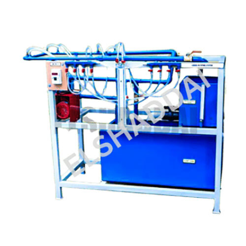
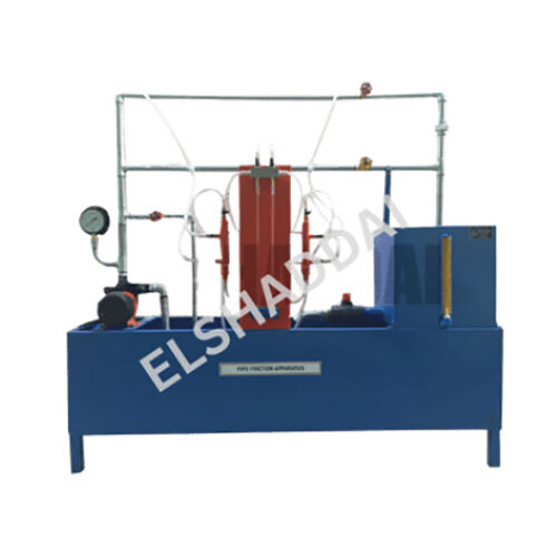
The Set-up consists of a 1/2 bend and elbow, a sudden expansion & sudden contraction fitting from 15 mm to 25 mm, ball valve and gate valve. Pressure tapings are provided at inlet and outlet of these fittings under test. A differential manometer fitted in the line gives pressure loss of individual fitting. Present Set-up is self-contained water re-circulating unit, provided with a sump tank and a centrifugal pump etc. Flow control valve and by-pass valve are fitted in water line to conduct the experiment on different flow rates. Flow rate of water is measured with the help of measuring tank and stop watchComprehensive Study of Pipeline LossesThis apparatus enables students and researchers to investigate both major losses due to pipe friction and minor losses due to pipe fittings and valves. With interchangeable pipe materials and diameters, it supports a wide array of experiments to understand hydraulic principles, providing real-time, precise measurements through high-precision manometers and a measuring tank.
User-Friendly Laboratory SolutionDelivered pre-assembled in a compact tabletop format, the setup is easy to install and transport. All control valves are manually operated for straightforward flow management, while overload protection enhances operational safety. Its corrosion-resistant construction and robust design make it a durable choice for repeated educational use.
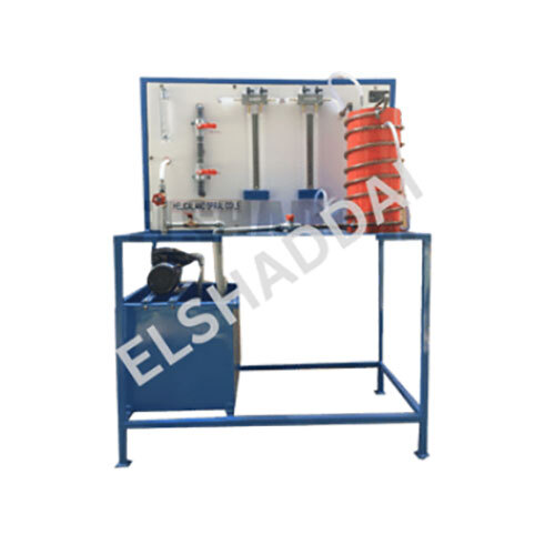
Accurate and Reliable MeasurementsEquipped with acrylic manometer tubes and a graduated scale, the apparatus offers clear readings for analyzing water pressure and flow. The system ensures high measurement accuracy and real-time demonstration of fluid mechanics principles as per ISO and BIS laboratory standards.
FAQ's of Major And Minor Losses In Pipe Line Apparatus:
Q: How does the apparatus demonstrate major and minor losses in pipelines?
A: It allows users to observe and measure major losses caused by pipe wall friction and minor losses due to bends, valves, and fittings using different pipes, fittings, and an accurate manometer. By comparing pressure drops, users can analyze the effects each scenario has on the hydraulic system.
Q: What materials are included with the apparatus for pipe and fitting options?
A: The setup includes interchangeable pipes made from PVC and brass in 15 mm and 20 mm diameters. Fittings such as elbows, bends, sudden expansions, sudden contractions, gate valves, and globe valves are provided for comprehensive experimentation.
Q: Where is this apparatus typically used?
A: It is primarily used in educational laboratories and hydraulic study centers for teaching and research related to pipe flow phenomenon, as well as in research institutes requiring demonstration and measurement of flow losses.
Q: When should I use the measuring tank and stop watch setup?
A: Use the measuring tank and stop watch to determine discharge rates accurately whenever you need to correlate pressure losses with actual water flow, particularly during experiments involving different pipe configurations or fittings.
Q: What process is followed to change pipe diameters or fittings?
A: To change pipe diameter or fittings, simply disconnect the current section and install the selected pipe or fitting; the tabletop, portable design and accessible mounting make this a quick process without specialized tools.
Q: How does the manometer assist in experiments?
A: The acrylic manometer, with its 0-300 mm measurement range and graduated scale, is used to monitor and record pressure differences across sections of the pipe or fittings, enabling accurate assessment of head loss according to experimental changes.
Q: What are the main benefits of using this apparatus in laboratory studies?
A: The unit provides hands-on experience with real-time visualizations, accurate measurements, and a safe, robust, and portable setup that complies with international lab standards, enhancing learning and experimental reliability.
 Send Inquiry


 Send Inquiry
